Why is zener diode used as a voltage regulator. In the circuit diagram of the Zener diode as shown in the figure when the value of V0 is 8 volt the current through Zener diode s i1 and when V0 is 16 volt the corresponding current is i2.

Zener Diodes Operation Symbol And V I Characteristics In 2021 Diodes Circuit Components Symbols
What is a zener diode.

. This is a diffused structure because both the substrates like P and N are. It occurs due to collision of crystal ions. The name zener diode was named after the American physicist Clarance Melvin Zener who discovered the zener effect.
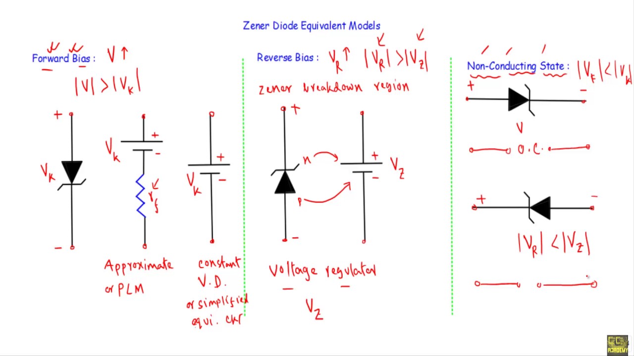
This is our I. 4- In which region zener diode can be used as a regulator. This is the complete equivalent circuit for the device for all dc calculations.
Draw Zener regulator circuit to obtain regulated DC voltage 68 V. Ideal diode in circuit. 1State what happens when light energy is passed through any medium and hence quote expressions representing Absorption spectrum and Transmission spectrum 2Use suitable diagrams to explain how total internal reflection can be achieved in a step index fibre cable 3Given that the refractive indices of core and cladding are 16.
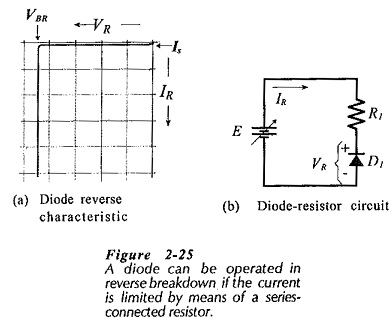
It is because the value of reverse resistance is so high r r 100 mw that is considered to. 4- In which region zener diode can be used as a regulator. The breakdown region graph of the actual Zener diode is not accurately vertical.
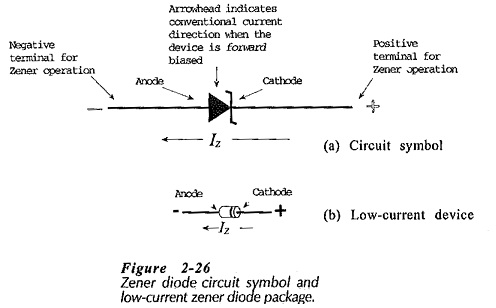
The circuit symbol of the Zener diode includes two tags at the finish of the bar where one is in the direction of upward and the other one is in the lower direction. V V Z I Z R Z. As indicated in the basic regulator design the required output voltage which is the equivalent Zener voltage Vz 47 Volts and the selected lowest Zener current is 100 microamps.
IiDraw the equivalent circuit of the zenner barrier circuit drawn above under fault conditions 7Use an idealized Vortex street diagram to describe the principles of operation of a vortex flowmeter 8A vortex flowmeter consisting of a rectangular bluff body is used to measure liquif flow rates in the range 01 to 103m per secondGiven. Draw equivalent circuit zener diode. You may assume that the Zener diode has no internal resistance a For V_s 40 V calculate the current for.
The Zener diode has a reverse-breakdown voltage at. The Zener diode construction is shown below. Equivalent circuit of zener diode 1 for ideal diode.
Zener breakdown voltage V2 6V. 1Use a block diagram to explain the operating principle of a cross correlation flowmeter stating all the necessary equations in your answer. 4Define maximum angle of acceptance of a fibre.
There are many ways in which a Zener diode is packaged. The diode usually consists of a p-n junction which is heavily doped. I 2 64000 15 mA.
2Draw and label the basic zener barrier circuit. The circuit symbol for a zener diodes characteristics in fig. The breakdown voltage of a zener diode is carefully set by controlling the doping level during manufacture.
Simply means that it connects to other circuit elements at connection points labeled a and b in the circuit below with the voltage v ab applied across the diode. LIKE COMMENT SHARE SUBSCRIBENon-Tech Channel. The graph shows that the Zener diode has some resistance.
Dynamic reverse bias breakdown resistance. 3Draw the equivalent circuit of the zener barrier circuit under fault conditions. A heavily doped semiconductor diode which is designed to operate in reverse direction is known as the Zener diode.
For the following circuit V_s is a variable DC voltage source and the Zener diode has a reverse breakdown voltage of V_z 5 V. Draw the diode equivalent circuit. 3Draw the equivalent circuit of the zener barrier circuit under fault conditions.
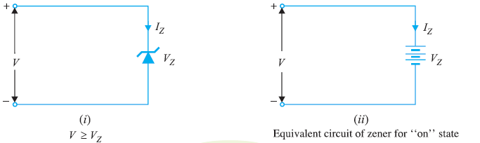
A zener diode is a p-n junction semiconductor device designed to operate in the reverse breakdown region. In a circuit an ideal Zener diode can be replaced by a voltage source V z when the Zener diode is operating in the breakdown region. In other words the diode which is specially designed for optimising the breakdown region is known as the Zener diode.
4Define maximum angle of acceptance of a fibre cableUse a suitable diagram to. Draw the equivalent circuit of an ideal zener in the breakdown region. In this video I showed how to replace zener diode with different equivalent circuits at different bias conditions.
2Draw and label the basic zener barrier circuit. An equivalent circuit is a combination of elements properly chosen to best represent the actual terminal characteristics of a device system or such in a particular. The output across the diode will be constant.
Find the value of i2i1. This is the complete equivalent circuit for the device. The equivalent circuit diagram is shown below.
Solution for 3- Draw the zener equivalent circuit. The Zener diode construction is shown below. The diode is designed to conduct the flow of current in the reverse direction after reaching a specified voltage.
It occurs in both rectifier and Zener diode at high reverse voltage. Draw equivalent circuit zener diode. Zener Breakdown Avalanche Breakdown Zener Breakdown 1.
A Zener diode is a semiconductor device that makes the current flow in the forward or in the backward direction. This implies that the maximum intended Zener current here is 100 microamps plus 10 milliamps which is 101 milliamps. The symbolic representation of Zener diode is shown in the figure below.
1Use a block diagram to explain the operating principle of a cross correlation flowmeter stating all the necessary equations in your answer. 1 Here the conduction is evident in both forward and reverses biases. So that it helps in differentiating these diodes from other types of diodes in the circuit.
Please provide a simple answer and explain. It occurs in Zener diode allow reverse voltage. 1State what happens when light energy is passed through any medium and hence quote expressions representing Absorption spectrum and Transmission spectrum 2Use suitable diagrams to explain how total internal reflection can be achieved in a step index fibre cable 3Given that the refractive indices of core and cladding are 16 and 15 respectivelycalculate.

Zener Diode As Voltage Regulator Tutorial
Zener Diodes Characteristics Circuit Symbol Equivalent Circuit
Zener Diodes Characteristics Circuit Symbol Equivalent Circuit

Zener Diode Circuit Curiosidades

An Equivalent Circuit With Zener Diode If The External Circuit With A Download Scientific Diagram
Zener Diode Equivalent Circuit Models Youtube
What Is A Zener Diode And How It Is Used As A Voltage Stabiliser Electronics Post
Mct Scs Thyristors Mct Acdc Electronics Projects
0 comments
Post a Comment